The first step is to obtain a CR2025, CR2032, or an otherwise compatible replacement battery with solder tabs.

Click on the image thumnails below to see the full-sized images.
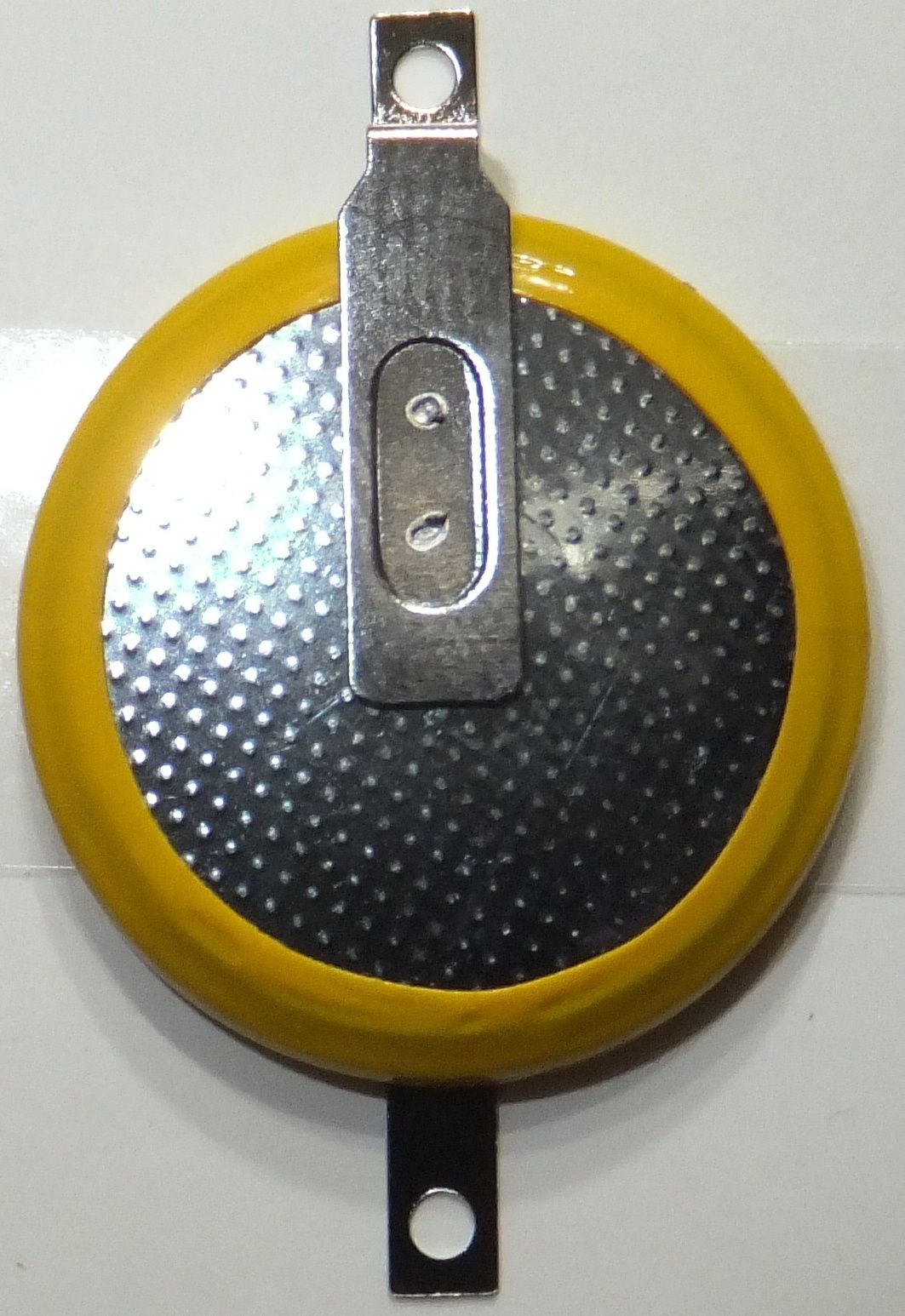
The first step is to obtain a CR2025, CR2032, or an otherwise compatible replacement battery with solder tabs.
The OEM batteries in these radios are typically CR2025's. The last 2 digits of this battery designation indicates the thickness of the battery. A CR2025 is 2.5 mm's thick. I chose to use a CR2032 which is 3.2 mm's thick; this choice was a matter of convenience as the CR2032 battery was cheaper and as far as I could tell otherwise compatible. My radio has been working just fine since I replaced the battery.
If you have any favorite frequencies programmed in make notes on what they are including offsets, PL tones, and the other minutia of that programming. You may also want to note the changes and settings of many of the menu selections.
Once you have a replacement battery the following steps should allow you perform the battery replacement.
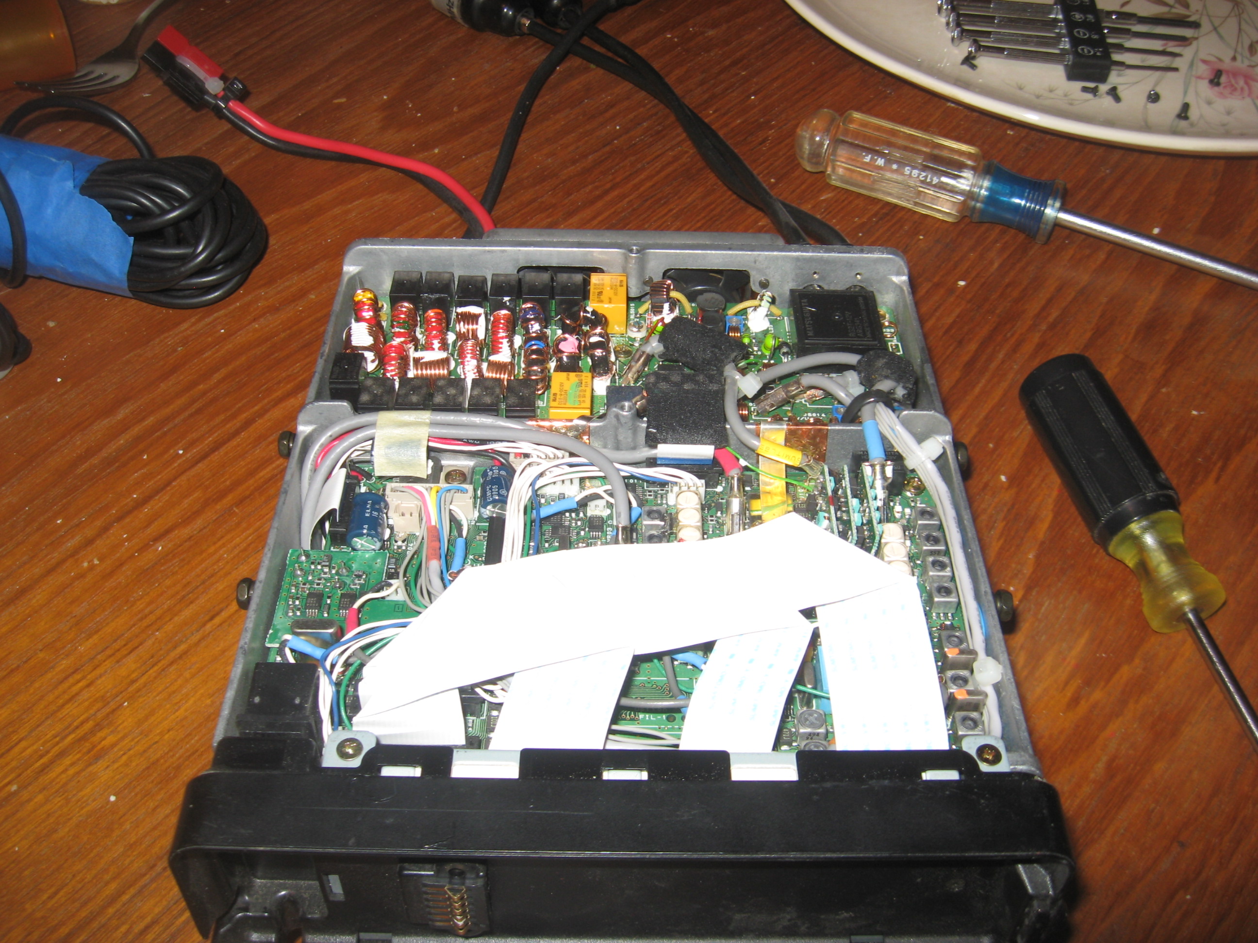
Get the soldering iron plugged-in and heating up. I also put a loop of tape sticky side out in small bowl to hold the fasteners which I would be removing. This reduces the probability that a tiny screw will join the countless other small fasteners which I have lost forever over the years.
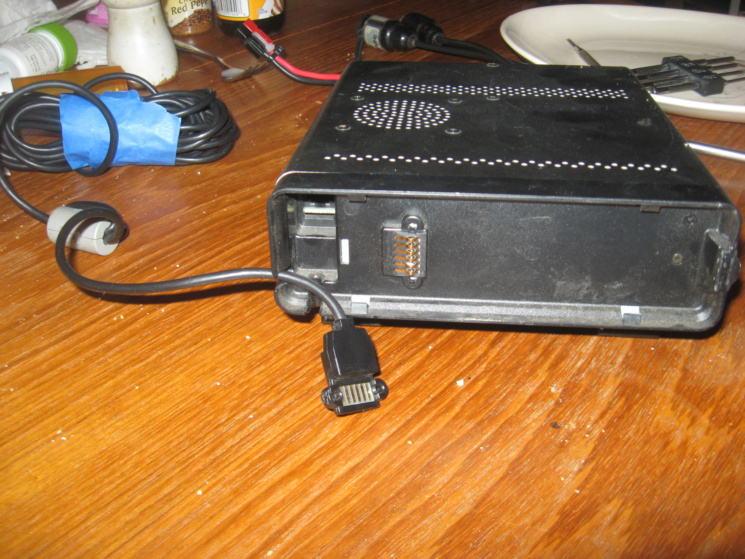
Remove from the radio chassis the cables that connects to the control head and to the microphone.
Remove the 12 screws which attach the radios metal covers: 6 for the top cover, and 6 more for the bottom cover. Be careful not to pull too hard on the speaker wires when you separate the covers from the chassis.
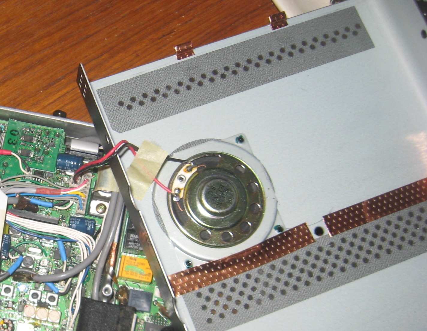
Unplug the speaker from the circuit board. and note where it plugs in.
Remove the 4 screws which atttach the plastic cover to the chassis: 2 on the top and 2 on the bottom.
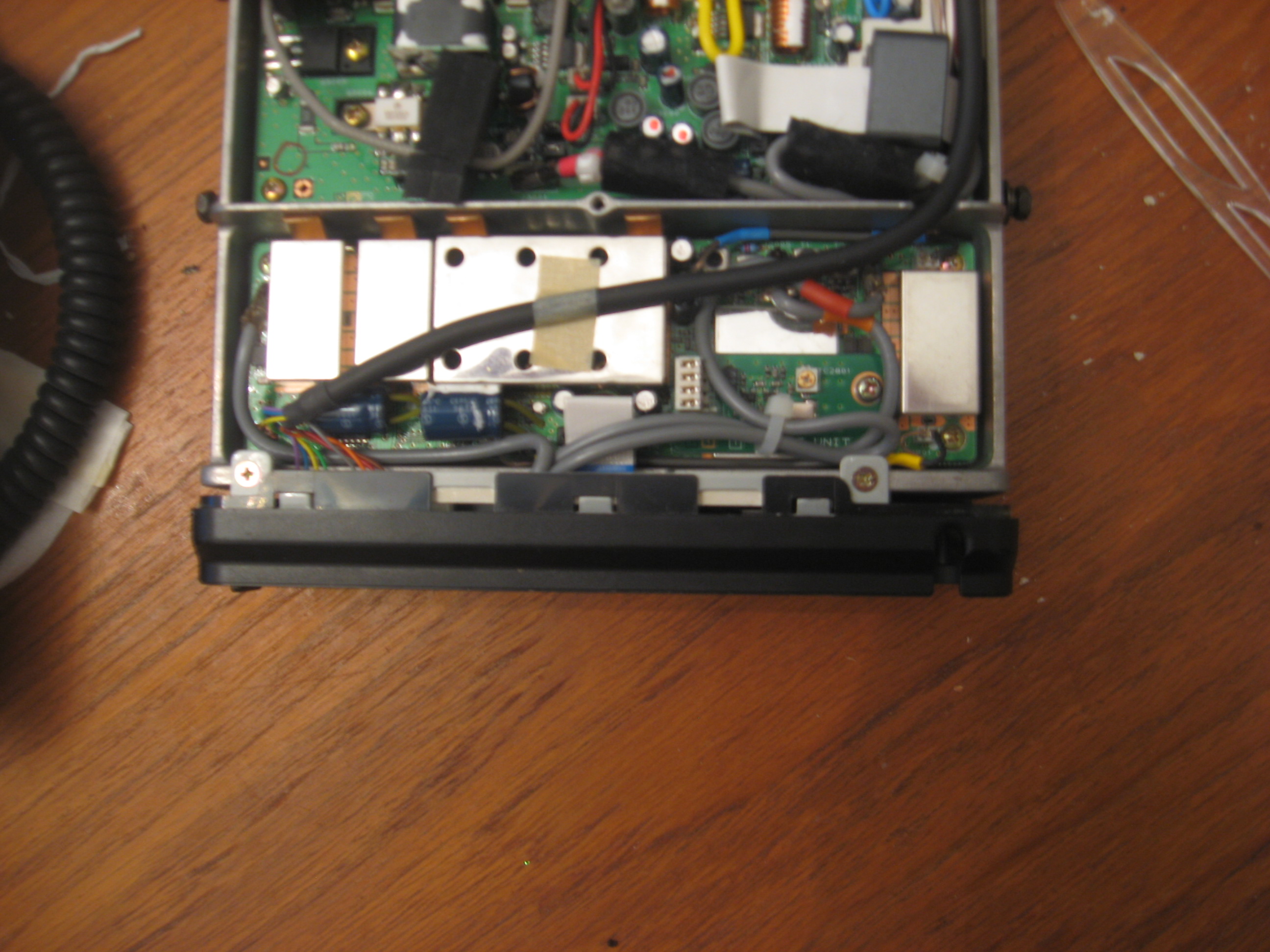
Lift the accessory pigtail (the one with the micro-DIN type connector) out of its notch in the rear of the chassis and remove the tape whic holds the cable in place near the front of the chassis.
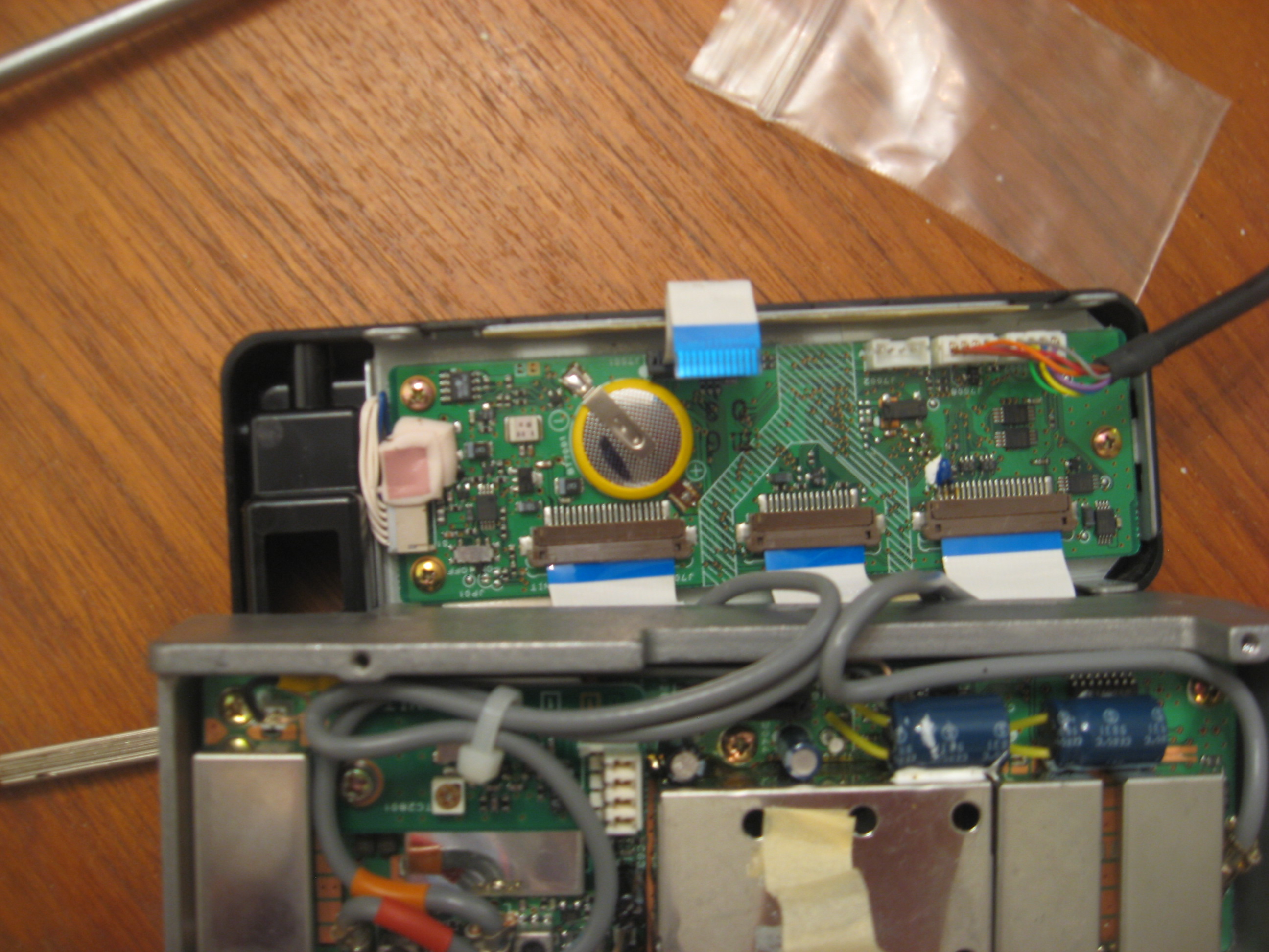
Disconnect the small ribbon cable that connects the plastic cover to the circuit board in the chassis. Lift the little tabs on both sides of the conector which the ribbon cable goes in to on the chassis-side circuit board and lift the ribbon cable out of the connector.
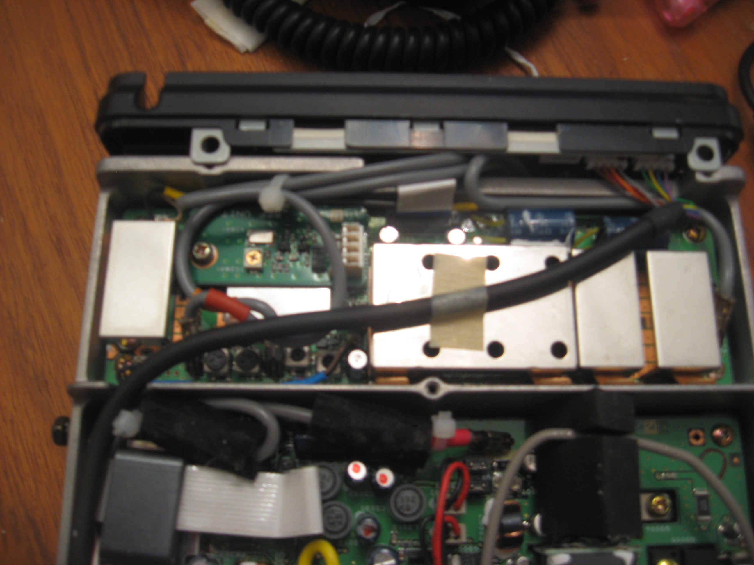
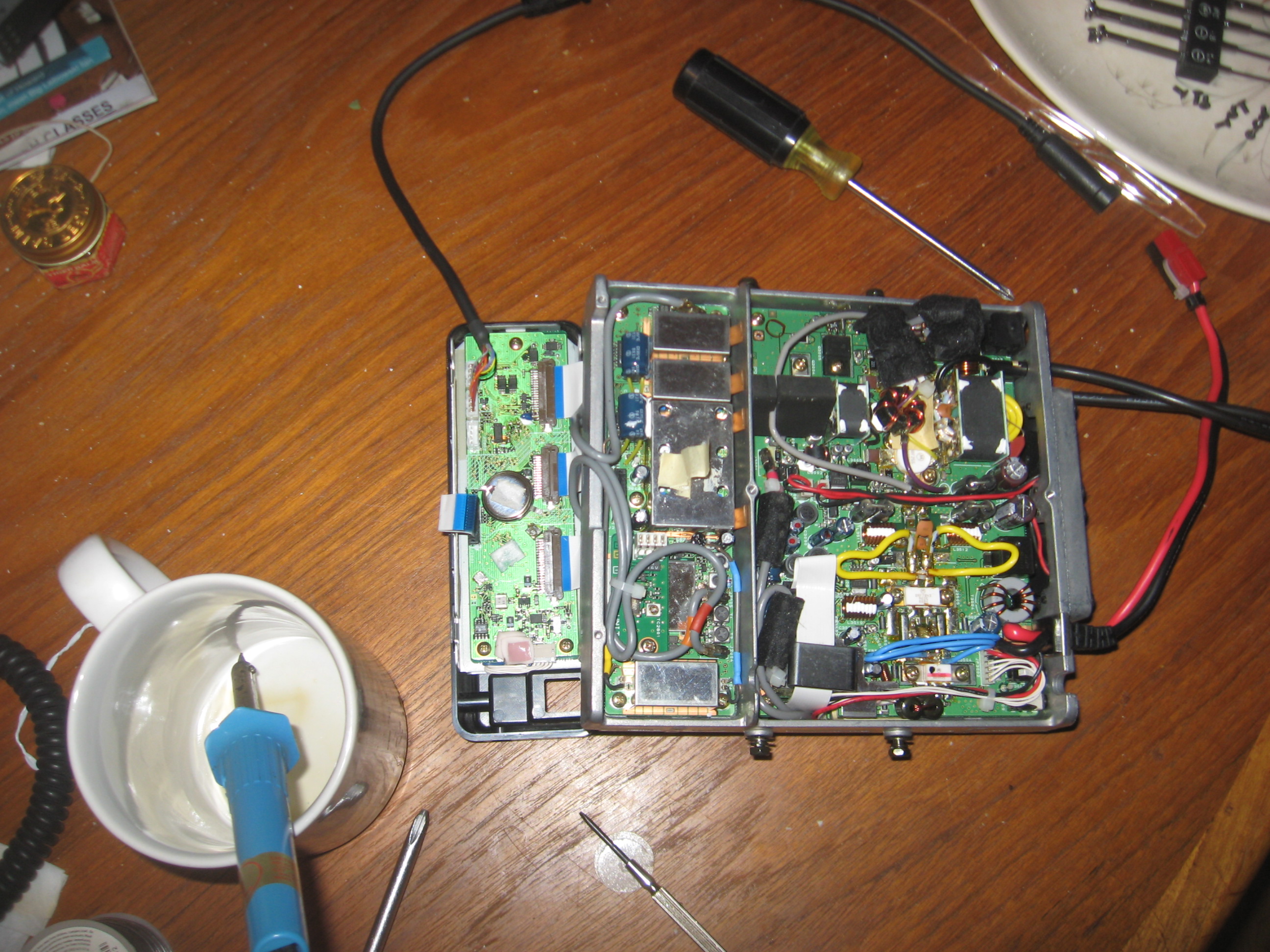
Tip the plastic cover down gently (see the photo) to access the battery which needs replacing.

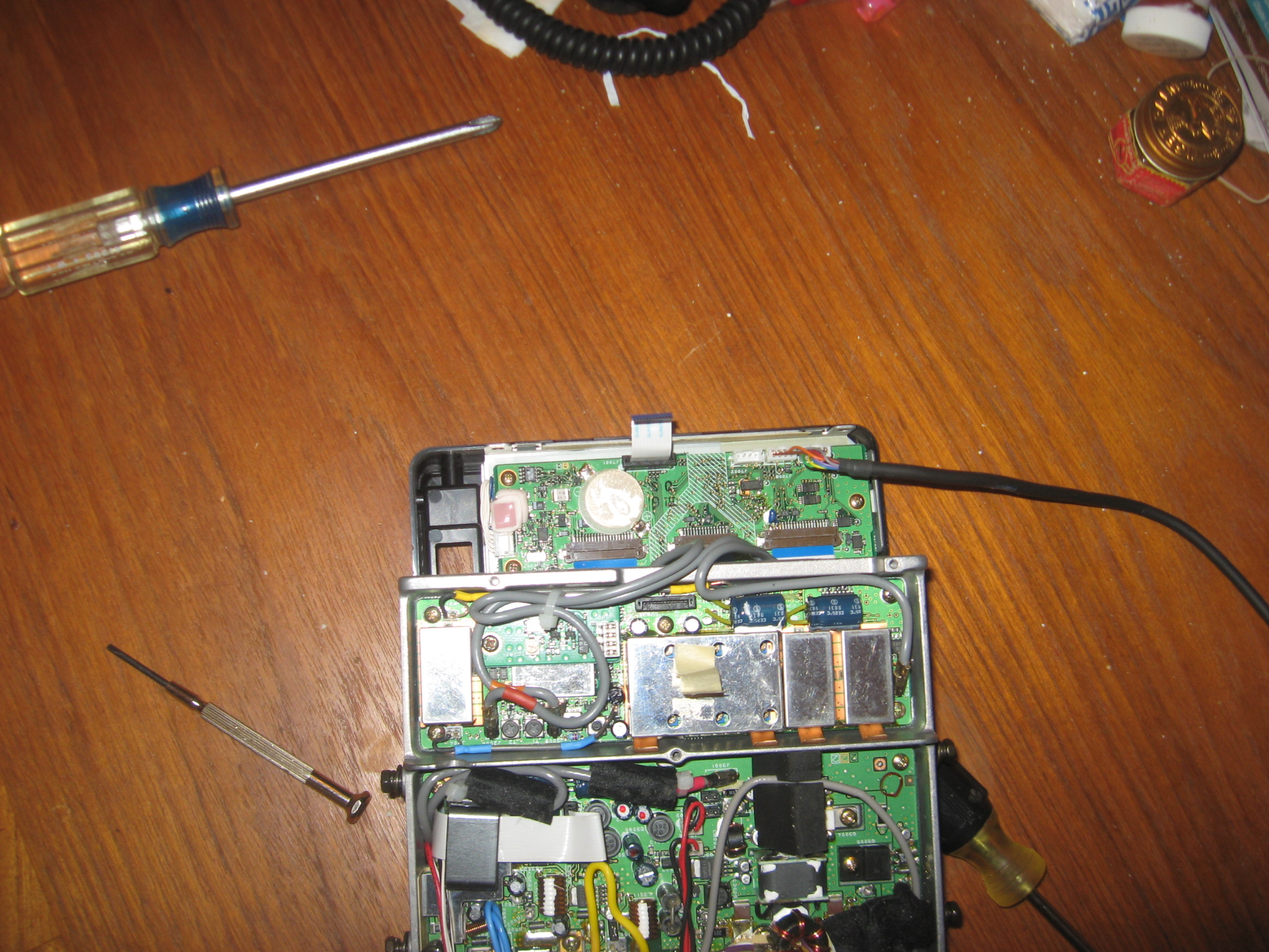
Note to polarities at the batteries solder points on the circuit board. My original CR2025 was positive-side up; however my replacement battery was negative side up. The plus-side solder point was marked on the circuit board and was confirmed by being connected to the plus side of the battery.
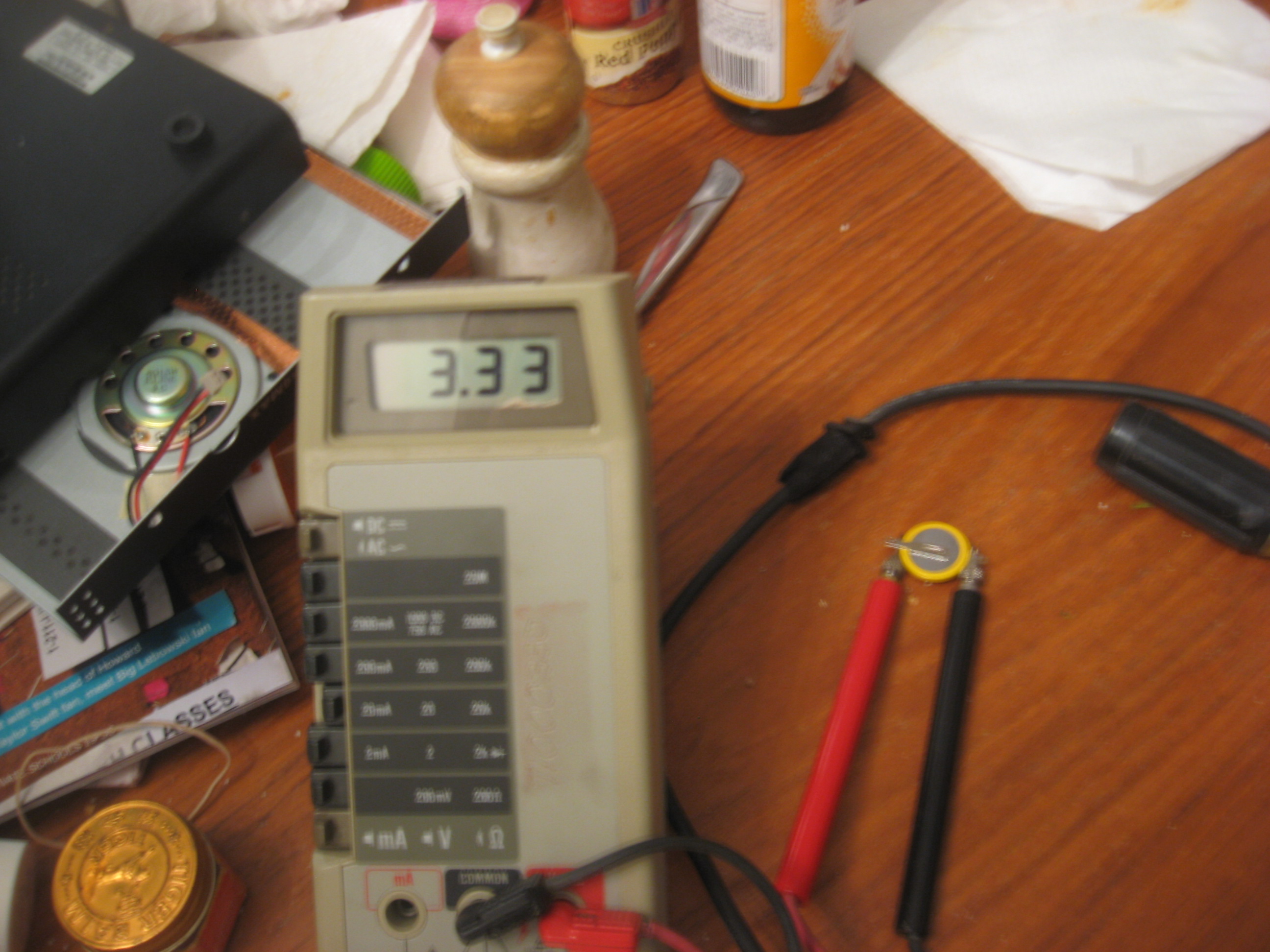
Use a voltmeter to verify the polarity of the replacment battery. You will see I marked my new battery with a Sharpie indicating that it was negative side up.
De-solder the old battery from the circuit board.
Orient the new battery on the cicuit board paying attention to the polarity of the solder tabs. and solder the new battery in place.
The original CR2025 had a clear plastic cover glued to its top. I suspected that the plastic cover was put there for a good reason so I put that plastic cover on the new CR2032 and covered it with a piece of electrical tape.
Begin the reassembly process by rotating the plastic cover back up towards the chassis.
Insert the ribbon cable in to the slot in the connector on the chassis-side circuit board. This is the most diffcult step of the entire repair. It comes apart easily but reconnecting it during the reassembly required a magnifier and at least 3 hands (I was born with only 2 hands). Be patient and e careful it can be done. I ultimately found that this step was easier without the plastic cover bescrewed in to the chassis but your experience may vary from my experience.
Power the radio up and check to see if the LCD display is blinking or you are seeing any errors. If you observe any blinking or errors the ribbon cable probably needs to be reinstalled. Check the connectors at both ends of the ribbon cable as either end may not be adequately seated in its circit board mounted connector. If the display looks happy and shows no errors then continue te reassembly process.
Screw the plastic cover to the chassis (if you have not already done so).
Insert the accessory pigtail in to its notch in the rear of the chassis and insall some new tape to hold the cable in place near the front of the chassis.

At this point you just need to reconnect the speaker, reinstall the covers, and reconnect the cables to the plastic cover.


 FJ45 Webmaster: Webmaster@FJ45.com
